
")
Combined distribution box (JP cabinet)
Belonging Category:
Keywords:
Combined distribution box (JP cabinet)
Product Details
Scope of Application
The TKDJP series outdoor integrated distribution box (hereinafter referred to as JP cabinet) is designed based on the requirements of power grid construction and transformation and power grid operation experience, following the principles of safety, economy, rationality, and reliability. It is a new type of outdoor integrated distribution box with multiple functions such as power distribution, control, protection, reactive power compensation, and power metering. It can also add leakage protection functions according to user requirements. The product has the advantages of novel and reasonable structure, accurate commissioning, high protection level, convenient installation, debugging, maintenance, and repair. The product conforms to GB7251.1 and has passed 3C certification. It is an ideal low-voltage complete set of devices in current power grid transformation.
The TKDJP series outdoor integrated distribution box is suitable for power distribution, metering, protection, and automatic reactive power compensation at the 0.4kV voltage level.
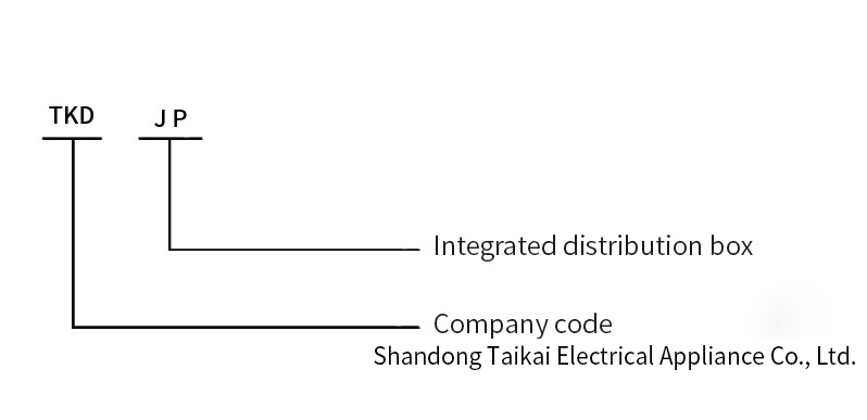
Model and Meaning
Standards Compliance
The TKDJP series integrated distribution box complies with the following standards:
GB/T 7251.1 Low-voltage switchgear and controlgear Part 1: General rules
GB/T 7251.2 Low-voltage switchgear and controlgear Part 2: Power switches and control devices
GB/T 4208 and IEC 60529 Degree of protection (IP Code)
GB/T 15576 Low-voltage complete set of reactive power compensation devices
Stand working conditions and installation conditions
Ambient temperature: Maximum temperature +40℃, 24-hour average temperature not exceeding 35℃, minimum temperature -25℃;
Relative humidity: ≤90% (relative ambient temperature 20℃~25℃). In areas with large diurnal temperature differences, measures such as ventilation, dehumidification, or heating should be taken to prevent condensation. Maximum wind speed: 35m/s;
Altitude: Not exceeding 2000m;
Environmental conditions: Suitable for outdoor installation, not suitable for places with fire, explosion hazards, severe pollution, chemical corrosion, and severe vibration;
Installation position: The inclination angle to the ground should not exceed 5º;
Pollution level: Grade 3;
Protection level: IP44.
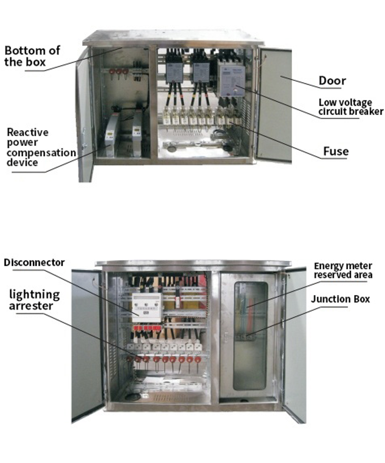
Structural Overview
Technical Performance Indicators
Rated voltage: AC400V;
Rated insulation voltage: AC690V;
Rated frequency: 50Hz;
Rated short-time withstand current: 20kA;
Rated peak withstand current: 40kA;
Rated current levels: 630A, 500A, 400A, 315A, 250A, 200A, 160A, 125A, 100A, 80A, 63/60A, 50A, 40A, 32A, 20A, 16A, 10A;
Capacitor grouping: Generally divided into 2, 3, 4, and 5 levels. If the user has special requirements, configure according to user requirements;
Feed lines: Generally divided into 2-3 lines. If the user has special requirements, follow user requirements;
Compensation method: Single-phase and three-phase combined compensation;
Controlled physical quantity: Reactive power or reactive current.
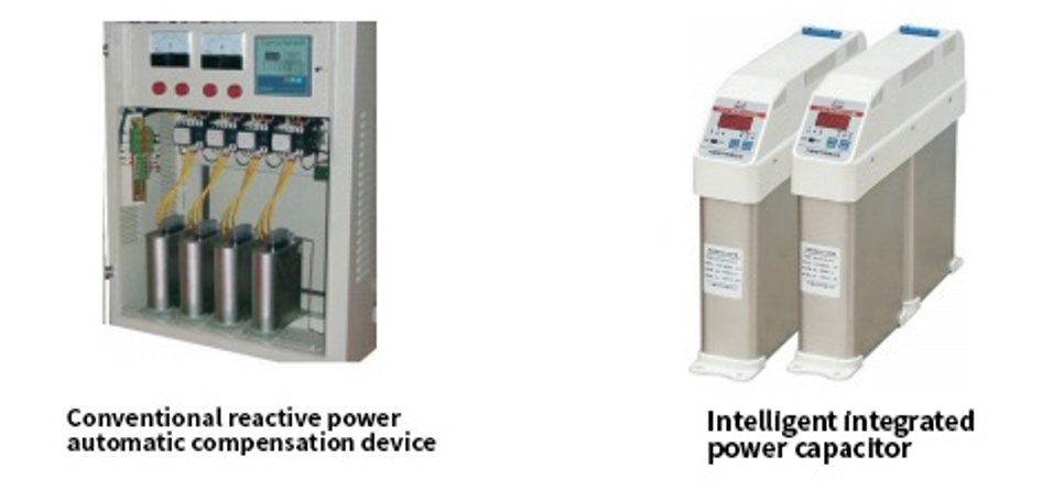
Automatic Reactive Power Compensation Device
Automatic reactive power compensation devices are divided into conventional automatic reactive power compensation devices and intelligent integrated power capacitors.
The conventional automatic reactive power compensation device consists of a reactive power phase automatic compensation controller (hereinafter referred to as the controller), switching capacitor contactors, self-healing capacitors, and isolating switches. The controller uses a high-performance 16-bit microprocessor as the core component and simultaneously takes three-phase voltage and three-phase current signals, providing up to 16 control circuits. Each controller provides three compensation schemes: full-phase compensation, full-common compensation, and common compensation plus phase compensation. It also provides 12 capacitor switching methods (output coding), and users can choose by modifying the control parameters. The control parameters are permanently saved once modified and are not lost when the power is off. The controller response time is less than 100ms. It uses fundamental power factor and fundamental reactive power to control the switching of the capacitor group. The switching is stable without switching oscillation, and it is not sensitive to voltage harmonics and current harmonic interference. It has a user-friendly human-machine interface and a beautiful appearance.
The intelligent integrated power capacitor uses a self-healing low-voltage power capacitor as the main body, an intelligent measurement and control processor as the control center, and uses microelectronic hardware and software technology to achieve zero-crossing control of the thyristor and delayed switching of the contacts of the mechanical magnetic latching relay, realizing the zero-crossing switching technology of the low-voltage power capacitor by the composite switching circuit of the mechanical magnetic latching relay and the thyristor, thereby compensating for the power factor of the 0.4kV low-voltage line. Compared with traditional low-voltage reactive power compensation products, it is simpler to operate, has a more intuitive interface, requires no professional skills for users, and has automatic cycle switching; it has fewer components, low temperature rise, small size, low power consumption, harmonic resistance, simple structure, easy to achieve standardization, normalization, flexible capacity configuration, safety, reliability, economy, and ease of use. Zero-crossing control reduces the impact of inrush current on the system voltage, stabilizes the system power grid, reduces equipment losses, and improves the service life of capacitors, and has significant energy-saving and environmental protection significance. It is not sensitive to voltage harmonics and current harmonic interference, has a user-friendly human-machine interface, and a beautiful appearance.
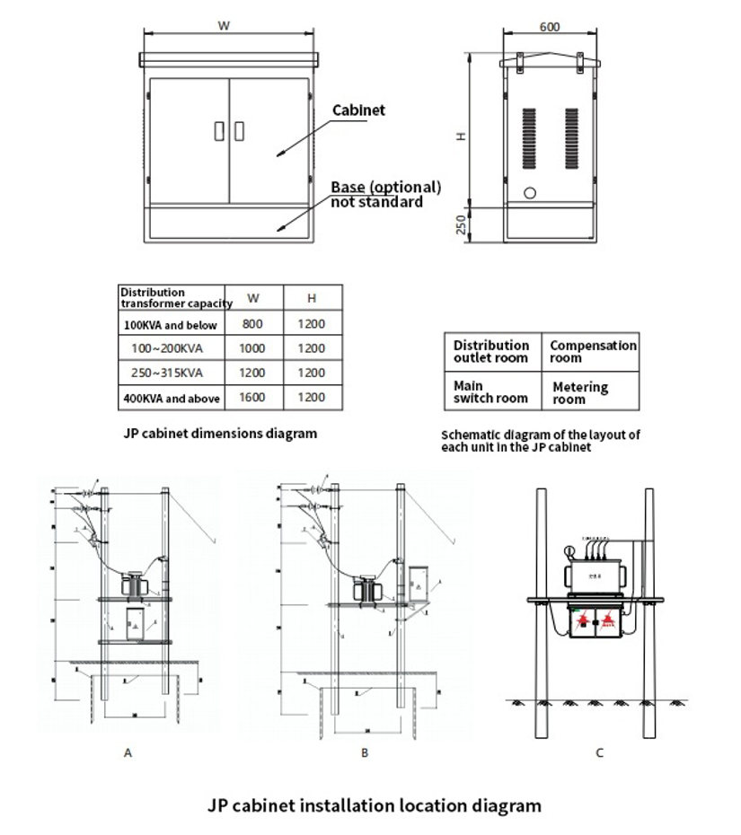
Appearance and Installation Dimensions
Usage and Maintenance Notices
Operation, maintenance, and repair of this product must be performed by qualified electrical personnel;
During maintenance, disconnect the power supply first and wait for the compensation capacitor to discharge completely before performing maintenance;
Reliable sealing measures should be adopted at the cable entry and exit points to ensure safe operation;
Circuit breakers should be regularly maintained;
If the JP cabinet uses a knife switch, the knife switch must be switched on and off under no-load conditions to ensure personal safety;
If the user selects a JP cabinet with a reactive power compensation device, the automatic reactive power compensation controller in the product should be operated and inspected strictly according to the product manual.
Accessory list and installation
The following information is required when the user places an order:
Scheme number, Rated current, Main circuit diagram, Auxiliary circuit diagram;
Transformer capacity, Feeder circuit number, Compensation capacity, Capacitor grouping requirements;
Input/output method, Mounting Method;
Requirements for the name, model, specifications, and quantity of main components such as controllers and circuit breakers;
Requirements for cabinet material, color, size, and spray marking;
Whether to add ground fault protection, automatic reclosing, and communication functions;
Whether to install supporting brackets;
Special environmental use requirements and other additional requirements
Related Products
Product Inquiry
You can leave your opinions and suggestions here, and we will reply to you in time
SHANDONG TAIKAI ELECTRIC APPLIANCES CO., LTD.
Service Hotline:
86-538-8520889
Tel:
86-538-8520889(Sales and Marketing Support)
86-538-5366875(General Department, Human Resources Department)
Email:tkdgdq@163.com
Address: No.11 Leigushi East Street,Taishan District,TaiAnCity, Shandong Province

WeChat Official Account
copyright © 2025 ShanDong TaiKai Electric Appliances Co., Ltd.